
Why Do Machine Vision Systems Miss Defects?
part 1
Why Do Machine Vision Systems Miss Defects?
On automated production lines, machine vision has been widely used for appearance inspection, dimensional measurement, character recognition, position judgment, and defect screening. Many vision inspection systems appear to operate with a very simple logic: the product enters the inspection area, the camera takes a photo, the software analyzes it, and then outputs OK or NG. However, once put into actual production, companies often encounter a very practical problem: the product clearly has a defect, so why did the machine vision system fail to detect it? This is missed detection in machine vision, often corresponding to a false negative in quality inspection.
When this problem occurs, it is easy to blame the algorithm first: Is the algorithm not accurate enough? Is the AI model not well trained? But in reality, many missed detections happen before the algorithm even starts working. If the camera does not obtain an image that is clear, stable, and distinguishable enough, the subsequent algorithm is facing incomplete visual data. Therefore, to understand machine vision missed detection, we must first start from the most basic step: Did the machine vision system actually "see" the defect?
1. The Nature of Missed Detection: The Algorithm May Not Be the First to Fail; the Information May Never Enter the System
In machine vision, missed detection usually means the product actually has a defect, but the vision system judges it as qualified. In other words, the true state is a Defective Product, but the system outputs OK. This is a typical Missed Detection. The corresponding problem is false detection: the true state is a Good Product, but the system outputs NG, which is a False Positive. Both problems affect the production efficiency and quality control of automated inspection systems. However, from a troubleshooting perspective, missed detection deserves special attention because it may mean the defect has not been fully converted into information that the machine can recognize.
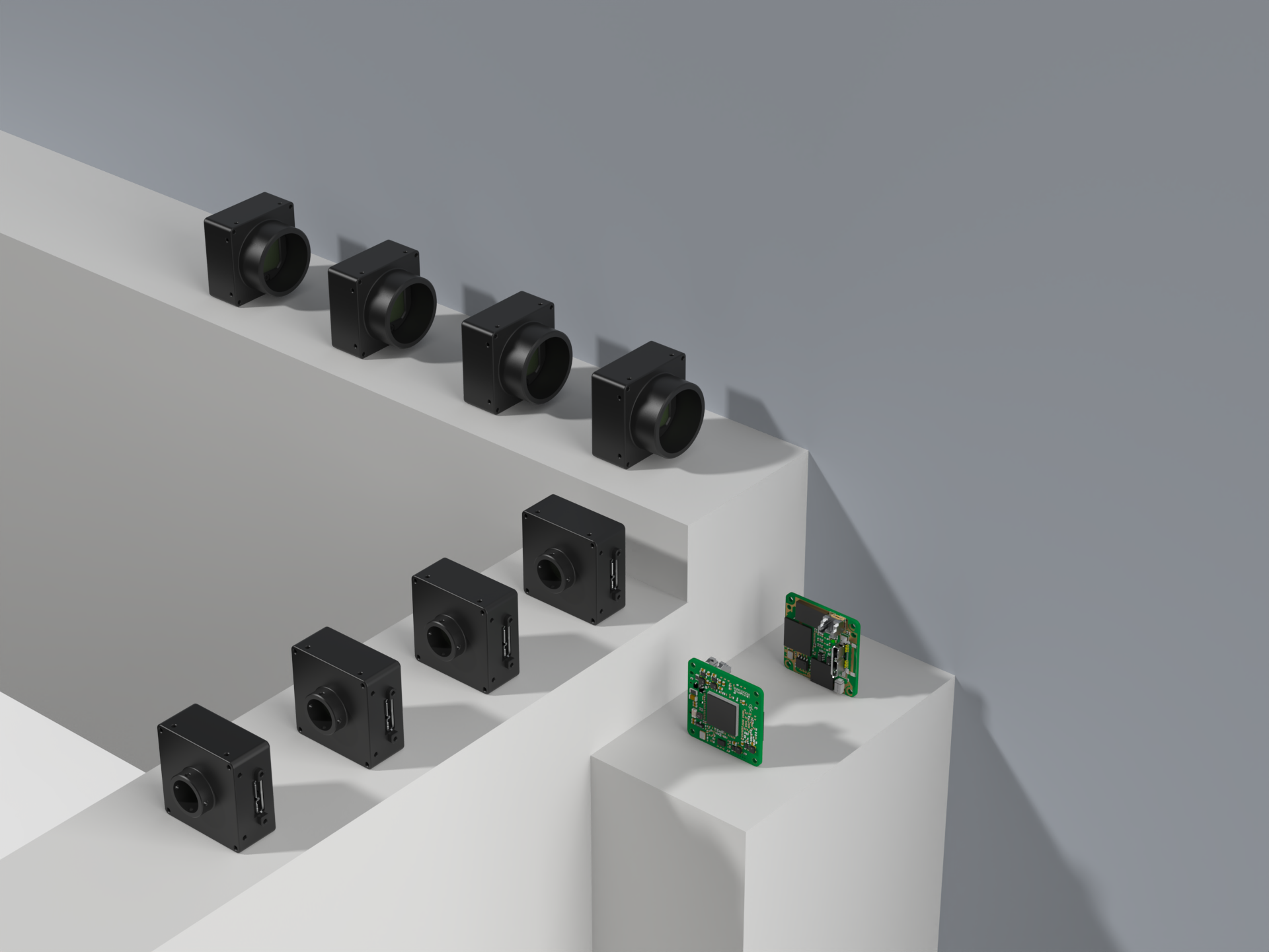
Before understanding missed detection, we need to change a common misconception: an industrial camera is not a device that completes inspection independently. A complete machine vision inspection system usually includes the object being inspected, lighting, lens, industrial camera, image sensor, trigger signal, image interface, industrial computer, vision software, inspection algorithm, and PLC or other automation equipment. Together they complete the following process: the object is illuminated by the light source, imaged through the lens, captured as an image by the camera, then processed and judged by the algorithm, and finally outputs a decision and drives the actuator. The role of the industrial camera is to convert the real scene formed by the optical system into a digital image, and the algorithm then analyzes these images. Therefore, if the previous imaging stage does not provide enough information, the later software cannot create that information out of thin air. This is why: Reliable Machine Vision Starts with Reliable Imaging.
2. The First Threshold of the Imaging Chain: Field of View, Resolution, and Pixel Density
The simplest type of missed detection is when the camera never sees the location of the defect. For example, a product is 100 mm wide, but the effective area actually covered by the camera is only 80 mm. If the defect happens to appear in the remaining 20 mm, then although the product has a defect, the image does not contain it. At this point, no matter whether traditional machine vision, deep learning, AI vision, pattern matching, or defect detection algorithms are used, the problem cannot be solved, because without image information there is no basis for detection. Therefore, the first step in designing a machine vision system is often not choosing an algorithm, but determining whether the camera's field of view fully covers the area to be inspected.
Field of View, or FOV, refers to the physical area the camera can cover at the actual working distance. If the FOV is too small, it creates a blind area. But if the FOV is too large, it can also cause problems. Suppose a camera has a horizontal resolution of 2448 pixels. When the horizontal field of view is 50 mm, the theoretical average pixel density is about 2448 ÷ 50 ≈ 49 pixels/mm. If the horizontal field of view is expanded to 200 mm, the pixel density drops to 2448 ÷ 200 ≈ 12.24 pixels/mm. In other words, the larger the physical area covered by the same sensor, the fewer pixels correspond to each actual object dimension. Therefore, the FOV is not simply "the larger the more convenient," nor "the smaller the more precise." What really needs to be found is a field of view that fully covers the inspection area while providing enough pixel information for the target defect.
Industrial cameras often use 2MP, 5MP, 12MP, 20MP, 25MP, or even higher-resolution sensors. But there is a very common misconception: the higher the pixel count, the smaller the defect that can be detected. This is not entirely true. What really matters is how many effective pixels the target defect ultimately occupies in the image. If a tiny defect ultimately occupies only a few pixels, its shape, edge, contrast, and texture may all be difficult to distinguish reliably. Conversely, if a reasonable combination of FOV, lens, and camera allows the same defect to occupy more effective pixels in the image, it becomes easier to identify as meaningful information. Therefore, camera resolution should be considered together with FOV, lens magnification, and target defect size.
For example, suppose the camera resolution is 2448 pixels and the horizontal FOV is 50 mm, then the pixel density is about 49 pixels/mm. If the target defect is about 0.1 mm, it theoretically corresponds to about 4.9 pixels in the horizontal direction. This is only an illustrative calculation for understanding pixel density and does not represent the actual detection limit. Real detection capability is also affected by lens resolution, focus, lighting, contrast, sensor noise, defect shape, defect orientation, and image processing. Therefore, "theoretical pixel size" and "actual detectable defect size" are not the same concept.
An industrial camera and lens form a complete imaging combination. Many projects pay close attention to pixel count when selecting a camera, but ignore lens resolution. If a high-resolution sensor is paired with a lens that cannot fully resolve those pixels, the result may simply be an image with many pixels but no real increase in detail. Therefore, a high-resolution camera does not automatically mean high-resolution imaging. A truly effective high-resolution vision system requires the sensor, lens, and FOV to match each other. The lens focal length, working distance, magnification, and sensor compatibility also affect the final image. If the focal length is not chosen properly, it may lead to an FOV that does not meet requirements, the product not fully entering the frame, obvious distortion at the edges, or an unreasonable working distance. For dimensional measurement and precision defect inspection, these problems can further affect inspection results.
3. Whether the Defect Can Be Stably Captured: Focus, Lighting, and Material Optical Properties
A photo that looks "generally clear" does not mean all inspection areas are in optimal focus. For example, if the product surface has height variations and the lens depth of field is insufficient, one area may be sharp while another area begins to blur. For ordinary photography, this slight blur may not be obvious, but for machine vision, the edge of a tiny defect may lose enough information because of it. Therefore, focus stability is one of the foundations of machine vision stability.
Lighting is an extremely critical part of machine vision. Even if a defect truly exists, if it does not form enough visual difference from the background, the camera will find it difficult to capture reliably. For example, a shallow scratch on a metal surface may have a very small grayscale difference from the surface under one lighting condition; change the lighting angle, and the scratch edge suddenly becomes visible. The product has not changed, the camera has not changed, and the algorithm has not even changed. What changed is the lighting condition. This shows that lighting is not just responsible for "illuminating the product"; it determines how the defect appears in the image.
Common lighting methods in machine vision include ring light, bar light, backlight, coaxial light, dome light, and dark field lighting. Ring light provides relatively uniform illumination from around the product; bar light can provide illumination in a specific direction; backlight creates a clear difference between the product contour and the background, often used for dimension and contour inspection; coaxial light is suitable for some flat or reflective surfaces; dome light reduces strong reflections on complex surfaces through large diffuse illumination; dark field lighting uses low-angle illumination to highlight certain surface defects and edge features. Therefore, the same defect may present completely different image characteristics under different light sources.
Materials such as metal, glass, and some plastics have obvious surface reflections. If light reflects directly into the lens, it may produce glare, hot spots, saturation, or strongly highlighted areas. As a result, the defect exists but is covered by strong reflection. What the camera finally obtains is reflection information, not defect information. Such problems should usually be addressed first from the lighting direction and camera angle, rather than directly changing the algorithm. Materials such as glass, transparent plastics, and films also involve optical phenomena such as reflection, refraction, transparency, and internal reflection. Therefore, the same defect observed from different angles may appear very obvious or almost invisible. This means that transparent material inspection usually requires simultaneous consideration of camera, lens, lighting, and viewing angle, rather than relying solely on image algorithms.
4. Stability in Dynamic Production: Motion, Exposure, Position, and Occlusion
On high-speed production lines, products are not stationary. If the object speed increases while the exposure time is too long, the product will move during exposure, ultimately forming motion blur. Originally sharp defect edges may become blurred areas. This change is especially obvious for targets such as small cracks, fine scratches, small holes, tiny characters, and sharp edges. Global Shutter allows the sensor to expose the entire frame within a more consistent time window. In contrast, Rolling Shutter exposes and reads line by line, which may produce geometric distortion for fast-moving targets. Therefore, in high-speed inspection, it is often necessary to consider the match among Global Shutter, exposure time, lighting, and object speed. However, it must be specially noted that Global Shutter does not mean there is absolutely no motion blur. If the exposure time itself is too long, the target will still move during exposure. So, shutter type and exposure time are two different issues.
Underexposure makes the image too dark, and overexposure makes the image too bright. But what industrial vision really needs is not a single "best-looking" image, but images that remain as stable and consistent as possible every time. Because machine vision algorithms usually rely on gray value, contrast, edge, texture, and brightness, if image brightness constantly changes, originally stable inspection rules may begin to fluctuate. When light is insufficient, Gain can be increased to brighten the image, but increasing Gain usually also increases image noise. If the goal is to detect very tiny defects, noise may make the distinction between defect and background more complicated. Therefore, in many scenarios, improving lighting is more reasonable than simply increasing Gain.
Vision systems are often designed for a relatively fixed production environment, but in actual production, products may shift, rotate, tilt, or change height. If the system assumes the product is always in a fixed position, then after the product shifts, the ROI may no longer cover the actual inspection area. In the end, the defect still exists, but the algorithm does not analyze it. Some defects are not due to insufficient resolution or poor lighting, but because the camera simply cannot see them from the current viewpoint. For example, a defect on the back of a part cannot be observed by a front-facing camera. At this point, even upgrading from 25MP to 50MP will not solve the problem. Because the problem is not resolution, but viewing angle or occlusion. Solutions may include changing the camera position, changing product orientation, adding cameras, or using multi-angle imaging.
Q&A for Part One
Missed detection means the product actually has a defect but the system judges it as OK, which is a False Negative; false detection means the product is actually qualified but the system judges it as NG, which is a False Positive. Missed detection is more alarming because it means the defect may flow into subsequent processes or reach the customer.
No. The algorithm can only analyze information already present in the image; it cannot create information that does not exist in the image out of thin air. If the defect does not enter the FOV, or is not captured during imaging, changing the algorithm or AI model cannot fundamentally solve the problem.
Because the key is not how high the camera's total pixel count is, but how many effective pixels the defect occupies in the final image. If the FOV is too large, lens resolution is insufficient, focus is inaccurate, or contrast is inadequate, a high-pixel camera may still produce an image with "many pixels but insufficient defect information."
Neither. A too-small FOV creates blind areas, while a too-large FOV reduces pixel density. The reasonable approach is: first ensure complete coverage of the inspection area, then ensure the target defect has enough pixels, while matching lens, sensor, and working distance.
No. Lighting determines how the defect appears in the image. The same scratch, pit, crack, or contamination may be very obvious or completely invisible under different lighting angles and methods. Lighting is part of the imaging design, not a simple accessory.
No. Global Shutter solves the issue of exposure timing consistency, but if the exposure time is still too long, the target will still move during exposure, and motion blur will still occur. Shutter type and exposure time must be considered together.
If the ROI is fixed at the original position while the product shifts, rotates, or changes height, the defect may move outside the ROI. At this point, although the defect is in the image, the algorithm does not analyze it, and the result may still be judged as OK.
Start with the imaging chain, not the algorithm. Consider adjusting the FOV, camera position, lens, working distance, product orientation, or adding cameras, using multi-angle imaging, or even changing the inspection station.
#MindVision
MindVision Technology Co., Ltd. is a professional domestic industrial camera manufacturer headquartered in Shenzhen, with production centers and R&D bases in Changsha (Hunan) and Wuxi (Jiangsu), employing nearly 300 people. Its product portfolio covers area-scan cameras, line-scan cameras, thermal imaging cameras, and stereo camera modules, with over 100 patents and software copyrights. The company is ISO9001 certified.
For more information or free selection consulting, please visit MindVision's official website or contact the sales team.
We’ll be glad to help you
Please Login
Full Name
Company Name
E-mail*
Country / Region
Your Needs / Application*
Verification code

Get in touch
Name*
E-mail*
Country*
Your Needs / Application*
