
How Do Robot “Eyes” and “Hands” Work Together?
A Guide to Vision Calibration in 3 Levels
How Do Robot “Eyes” and “Hands” Work Together?
A Guide to Vision Calibration in 3 Levels
If you’ve ever watched a robotic arm precisely pick up randomly placed parts from a bin, or sort packages speeding down a conveyor belt, you’ve witnessed a small miracle of engineering. But behind every smooth pick-and-place operation lies a quiet, invisible hero: Hand–Eye Calibration.
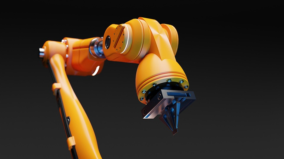
Think of a robot as a super-smart baby. Its “hand” (the arm) is strong but basically blind. Its “eye” (the camera) can see everything but has no idea where it is in the real world. Hand–eye calibration is the process of giving the robot a pair of glasses — so that what the camera sees can be translated into what the robot can actually reach and grasp.
What the camera sees → What the robot understands.
Camera coordinates → Robot coordinates.
In this post, we’ll break down the three most common calibration methods you’ll encounter in real-world factory floors. And to make things practical, we’ll show you how MindVision industrial cameras are used in each scenario — focusing on their 2D camera lineup, with general guidance for 3D applications.
Level 1: 9-Point Calibration – The “Quick Fix” for Flat Surfaces
If your task is simple — all parts lie flat on a plane (e.g., on a conveyor belt or worktable) — then 9-point calibration is your best friend.
How it works: Imagine working with a 2D map. The camera sees pixel coordinates (u, v), while the robot moves in XY coordinates (in millimeters). 9-point calibration builds a mathematical bridge (an affine transformation) that converts pixels to robot coordinates on the fly.
Why 9 points? Theoretically, 3 points are enough. But in practice, camera lens distortion and robot repeatability errors are inevitable. By using a 3×3 grid of 9 points and applying a least-squares fit, we get a solution that averages out small errors.
Bottom line: 9-point calibration is a fast, reliable 2D coordinate converter. If your parts stay flat and don’t change height, this is all you need.
Engineering note: The affine model does not require the camera to be perfectly perpendicular, but we recommend keeping the optical axis within ±5° of the surface normal. Beyond this, perspective distortion becomes non‑linear and a homography‑based calibration is preferable.
Level 2: 12-Point Calibration – Fixing the “Rotation Mismatch”
9-point calibration works great — until your robot needs to rotate.
Here’s the problem: in many setups, the robot’s rotation center (the axis of its gripper) does not coincide with the camera’s field-of-view center. When the gripper rotates, the grasping point shifts unpredictably. The 9-point matrix alone can’t correct for this.
Enter 12-point calibration. It’s not a replacement — it’s a patch:
- The first 9 points build the standard XY mapping.
- The additional 3 points are collected with the gripper rotated to three different angles (e.g., 0°, 45°, and 90°).
- With these 12 data points, the algorithm calculates the actual rotation center and effectively “translates” it to align with the vision center.
Bottom line: Use 12-point calibration when you need to grasp with a specific angle and your rotation axis is offset from the camera’s line of sight.
Level 3: OpenCV Hand–Eye Calibration – Conquering 3D Space
Now we’re entering the big league. What if parts are stacked randomly in a bin? Or what if you need to spray paint a curved car door? In these cases, you not only need to know where the target is (X, Y, Z), but also how it’s oriented (roll, pitch, yaw).
This is true 3D hand–eye calibration, and OpenCV provides a dedicated function: cv2.calibrateHandEye().
How it works: Unlike the simpler 2D methods, this solves a matrix equation called AX = XB. The process requires:
- A camera (or multiple cameras) that can perceive depth — this could be a stereo camera, a structured-light system, or even a single 2D camera combined with a laser rangefinder.
- A calibration board attached to the robot’s end-effector.
- Multiple robot poses — at least 3 non-parallel rotations in space.
- For each pose, you record both the robot’s pose (gripper2base) and the board’s pose relative to the camera (target2cam), computed via OpenCV’s
solvePnP(). Thencv2.calibrateHandEye()computes the full 3D transformation.
The “secret sauce”: Why must the robot move in non-parallel rotations? Because pure translations would make the math “ill-conditioned” — the solution would be unstable and inaccurate. Only varied rotations lock in a unique, reliable answer.
Bottom line: OpenCV hand–eye calibration is the heavyweight solution for 3D environments where parts are stacked, tilted, or randomly oriented.
Practical tip: In production, we recommend collecting 10–20 diverse poses (not just position, but also orientation axes). More than 30 poses brings diminishing returns while increasing computation time.
A Critical Enabler: Time Synchronization
In high-speed production lines, multiple cameras capture moving parts simultaneously. If their timestamps are out of sync, image stitching errors and measurement deviations occur. Robotic grasping requires strict synchronization between the vision system and the robot controller — even a slight delay can cause a miss or collision.
This is where Precision Time Protocol (PTP) comes in. MindVision’s GigE series MV-GES240GC/GM now supports IEEE 1588 PTP, achieving sub-microsecond (<1 μs) time synchronization across devices — thousands of times more precise than traditional NTP (millisecond-level).
With PTP, MindVision cameras can synchronize with master clocks, PLCs, robot controllers, and other PTP-enabled devices seamlessly. This is critical for multi-camera systems in PCB inspection, high-speed sorting, and robotic guidance applications.
Quick Decision Guide: Which One Should You Use?
| Scenario | Recommended Method | Suggested Hardware |
|---|---|---|
| Parts lie flat, same height; no gripper rotation needed | 9-point | MindVision GigE series (e.g., MV-GES240GC/GM) |
| Parts lie flat, but gripper rotation is required for precise pick | 12-point | MindVision compact camera (e.g., MV-MS136GM) |
| Parts are stacked in 3D, randomly oriented | OpenCV hand–eye | Multi-camera stereo or 2D camera + distance sensor (consult MindVision for customized 3D solutions) |
| Multi-camera high-speed line | + PTP synchronization | MindVision GigE cameras with PTP support |
Frequently Asked Questions (FAQ)
Strictly speaking, the affine transformation model used in 9-point calibration does not require the camera to be exactly perpendicular — it can handle a certain degree of perspective distortion as long as all calibration points are coplanar; however, significant tilt introduces non‑linear distortion that the affine model cannot correct, so in practice we recommend keeping the camera optical axis within ±5° of the surface normal, and if you must mount the camera at a large angle, you should consider performing a full perspective‑projection calibration (homography) instead of the affine model.
Yes — using more points generally improves the robustness of the least‑squares solution against measurement noise, and in fact the name “9‑point calibration” is a convention rather than a strict requirement, as many engineers use 16 or 25 points for larger fields of view or when higher accuracy is needed, though the trade‑off is increased operation time for touching off each point; we recommend at least 9 points as a minimum, and you should use more if your robot’s repeatability is marginal or your camera has significant lens distortion.
They address different problems: intrinsic calibration (focal length, principal point, distortion coefficients) models the internal geometry of the camera and corrects lens distortion, while 9‑point calibration establishes the external coordinate mapping between the camera and the robot; in practice, you should perform intrinsic calibration first to undistort the images, and then perform 9‑point calibration using the undistorted pixel coordinates, because failing to correct distortion — especially with wide‑angle lenses — can cause systematic errors of several pixels near the image edges.
No — 12‑point calibration is not an alternative model but rather a supplemental procedure that adds rotation‑center compensation on top of the standard 9‑point affine mapping, so if your gripper does not rotate relative to the work plane, 12‑point calibration provides no additional benefit and the extra data points are unnecessary; you should use 9‑point when rotation is not involved, and use 12‑point when rotation is involved and the rotation center is offset from the camera’s reference point.
The mathematical minimum is 3 non‑parallel poses, but in practice we recommend 10–20 poses with diverse orientations — varying not only the gripper position but also its rotational axes — because more poses improve the conditioning of the AX = XB system and reduce the influence of measurement noise; however, diminishing returns set in beyond 20–30 poses, as the calibration time increases while accuracy gains become marginal, and you should also ensure that the poses are well distributed in the robot’s workspace rather than clustered in a small region.
For 2D methods (9‑point and 12‑point), the standard approach is cross‑validation: leave out one calibration point, recompute the transform with the remaining points, and compare the predicted coordinate against the actual measured coordinate at the left‑out point, then repeat for each point and compute the RMS error; for 3D OpenCV calibration, the primary metric is reprojection error — project the 3D calibration points back into the image plane and compute the average pixel distance between the projected points and the detected corners, and a reprojection error below 0.5 pixels is generally considered good for industrial applications.
Yes — the board should be flat (surface flatness ≤0.1 mm over the board area) and rigid (no warping under temperature changes or handling), with ceramic or glass boards offering better flatness than printed paper on cardboard; additionally, the corner detection algorithm relies on clear contrast between the checkerboard squares, so matte‑finished boards are preferred to avoid glare, and for large‑scale applications (e.g., 1‑meter‑plus fields of view) you should consider using custom‑sized boards with large enough patterns for reliable detection at the working distance.
In the Eye‑to‑Hand configuration (camera fixed outside the robot), the camera is mounted on a stationary tripod or frame, the transformation matrix X describes the fixed pose of the camera relative to the robot base, and the calibration board is attached to the robot end‑effector; in the Eye‑in‑Hand configuration (camera mounted on the robot arm), the camera moves with the robot, the transformation matrix X describes the pose of the camera relative to the robot end‑effector, and the calibration board is placed at a fixed position in the workspace — the mathematical formulation differs in how the pose data are arranged, and OpenCV’s calibrateHandEye() handles both cases through the ordering of input parameters.
The calibration accuracy cannot exceed the repeatability of the robot itself, as the calibration result is fundamentally bounded by the precision of the physical points you record, so with ±0.2 mm repeatability your overall system accuracy will be in that same order of magnitude; to mitigate this, you can use multiple measurements at each calibration point and average them, use a larger number of points (e.g., 16 or 25) to reduce the influence of individual positioning errors, or consider using an external measurement device (e.g., a laser tracker) for ground‑truth point acquisition if the robot’s repeatability is the limiting factor.
Changing lighting intensity or pattern does not affect the calibration as long as the camera can still reliably detect the calibration points; however, changing lens aperture or focus may slightly alter the effective focal length and distortion profile, so for high‑precision applications we recommend re‑calibrating after any mechanical adjustment to the lens, and replacing the lens or moving the camera requires a complete re‑calibration because the extrinsic parameters (camera‑to‑robot transformation) have changed — a good practice is to document the calibration date, hardware configuration, and resulting reprojection error for traceability.
Final Thoughts: Engineering Is About Choosing the Right Tool
None of these methods is “better” than the others. They are different answers to the same core question under different constraints: How do I connect what the camera sees with what the robot does?
A seasoned engineer knows that reaching for a full 3D solution when a 2D calibration would do is overkill — it costs more, takes longer to debug, and introduces unnecessary complexity. The real art lies in choosing the simplest tool that gets the job done well.
And with the right hardware — like MindVision’s comprehensive lineup of industrial cameras, from entry-level GigE models to high-resolution compact cameras — you have the flexibility to build a vision system that fits your specific application, whether it’s a simple flat-picking station or a complex 3D bin-picking cell (with customized 3D sensors if needed).
I hope this guide helps you pick the right key for your lock.
#MindVision
Selecting the right industrial camera for your vision system is just as critical as picking the right calibration method. Resolution, frame rate, spectral range, environmental protection (IP rating), interface (GigE, USB3, 10GigE), and budget all play a role. A mismatched choice can lead to missed detections, false positives, system instability, and ultimately lower ROI.
MindVision offers free professional camera selection consulting for a wide range of applications — from factory automation and robotic guidance to logistics sorting and even specialized environments like aquaculture or agriculture. Our engineering team can analyze your specific scene: object size, motion speed, lighting conditions, mounting space, and detection accuracy goals. We then recommend the optimal camera, lens, lighting, and housing (including waterproof/anti-vibration enclosures) to fit your project.
Whether you are a system integrator or an end user, we are happy to provide technical support, sample testing, and on-site demonstrations. Contact us to discuss your requirements — we speak both engineer and business.
We’ll be glad to help you
Please Login
Full Name
Company Name
E-mail*
Country / Region
Your Needs / Application*
Verification code

Get in touch
Name*
E-mail*
Country*
Your Needs / Application*
