
Machine Vision for Large Cylindrical Battery Cells: A Complete Inline Inspection Guide
 The Large Cylindrical Battery Boom—and Its Yield Challenge
 The Large Cylindrical Battery Boom—and Its Yield Challenge
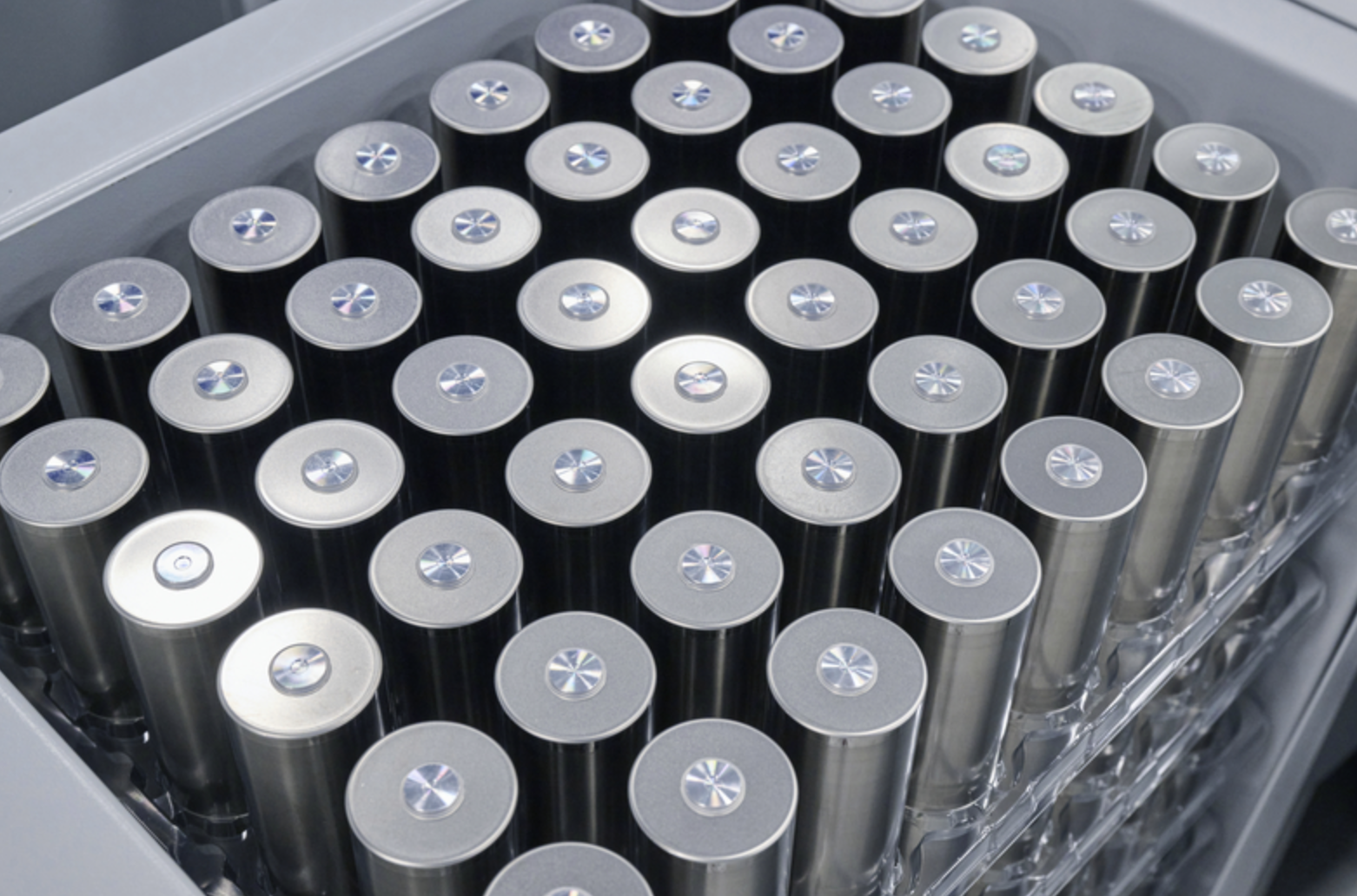
When Tesla unveiled the 4680 cell (46mm diameter × 80mm height) at its September 2020 Battery Day, it promised roughly five times the energy of the legacy 2170 format. The 46-series has since grown into a family: the 4695 targeting passenger vehicles, the 46120 aimed at long-range applications, with BMW's sixth-generation batteries, EVE Energy, BAK, Panasonic, LG Energy Solution and Samsung SDI all publishing mass-production roadmaps.
The appeal is clear: higher energy density, fewer structural parts, lower cost per Wh, and a format that fits naturally into CTC (Cell-to-Chassis) designs. The catch lies in manufacturing. The tabless (all-tab) architecture introduces brand-new processes—tab forming and current-collector disc laser welding—that make yield ramp-up far harder than for prismatic or pouch cells.
Cycle time raises the stakes further. Giga-scale production lines for large cylindrical cells typically run at 200-300 PPM (cells per minute), leaving only a few hundred milliseconds of inspection window per cell. Manual visual checks are neither feasible nor reliable at this pace, so inline machine vision has become standard equipment at every station. Camera frame rate, line rate, resolution and interface bandwidth now directly determine whether an inspection system can keep up with the line.
1Six Vision Inspection Stages in Large Cylindrical Battery Manufacturing
From electrode coating to final outgoing inspection, large cylindrical battery inspection spans six process stages. Each stage has distinct inspection targets, defect signatures and imaging challenges—and therefore very different camera requirements.
Stage 1Electrode Coating and Slitting Inspection
Targets and defects: Coating determines the areal density consistency of the electrode. Typical defects include coating weight variation, scratches, exposed foil, bubbles, particles and dark spots. At the slitting station, micron-scale edge burrs must be controlled—a burr that punctures the separator becomes an internal short-circuit hazard.
Imaging challenges: Coating webs run at tens to over a hundred meters per minute, at widths often exceeding 600mm, while target defects measure only tens of microns. The resulting data throughput is enormous, and the highly reflective foil surface demands precise lighting and exposure control.
Camera requirements: A line scan camera for electrode coating should deliver 8K/16K resolution at line rates of 80 kHz or higher, with CoaXPress or fiber interfaces to carry the data stream. For burr measurement, pair the camera with a telecentric lens to eliminate perspective error and guarantee micron-level accuracy—while also supporting electrode alignment and web guiding.
Stage 2Cell Winding Alignment and Overhang Measurement
Targets and defects: Winding is the heart of cylindrical cell manufacturing. In tabless designs, multiple tab layers must align within microns; the system must also measure overhang inline—the margin by which separator and anode extend beyond the cathode—and detect winding misalignment, spiraling and core deformation.
Imaging challenges: The winding head rotates at high speed with the target in constant motion. Electrode and separator edges are thin and low-contrast, leaving only microseconds for edge extraction and dimensional computation per frame.
Camera requirements: A high speed camera for cell winding should offer 5-12MP resolution at frame rates of 200 fps or above with a global shutter to freeze motion without blur. GigE and 10GigE interfaces simplify multi-camera networking and long cable runs around the winding machine.
Overhang is the safety margin by which the separator and anode extend beyond the cathode at each edge of the wound jellyroll. Too little overhang risks anode-to-cathode contact and internal short circuits; too much wastes active material and capacity. Because it directly affects cell safety, overhang must be measured on every cell, at full line speed—one of the most demanding tasks for battery cell winding alignment systems.
Stage 3Tab Forming and Busbar Welding Inspection
Targets and defects: This stage is unique to large cylindrical cells. After tab forming (flattening), the end face must be checked for flatness, folds and damage. After the current-collector disc is laser-welded—often referred to as tab and busbar welding inspection—the weld must be verified for continuity, blowholes, cold welds and misalignment. Can inspection covers surface defects (scratches, dents), groove dimensions, wall-thickness consistency, plus the filling port and safety vent.
Imaging challenges: Weld zones are highly reflective, and plasma glare during welding easily overexposes conventional cameras, washing out weld detail. Weld bead geometry is inherently three-dimensional, so 2D grayscale information alone cannot reliably flag cold welds.
Camera requirements: Use a high dynamic range (HDR) area scan camera (12MP+, global shutter) to tame reflections while preserving weld texture, fused with a 3D camera that reconstructs bead topography—an integrated 2D+3D approach. For can exteriors, a multi-camera ring arrangement provides full circumferential coverage.
Stage 4SWIR Electrolyte Level and Residue Detection
Targets and defects: After filling, the electrolyte level must be verified and the filling port checked for residue—leftover electrolyte contaminates downstream welding stations and corrodes the can.
Imaging challenges: Electrolyte is nearly transparent under visible light and blends into the can background. In the 900-1700nm short-wave infrared (SWIR) band, however, it exhibits characteristic absorption, making the fill level and trace residue clearly visible.
Camera requirements: Choose a SWIR electrolyte detection camera built on an InGaAs sensor covering 900-1700nm, paired with SWIR illumination for transmission imaging. Inline systems typically cross-check the vision result against gravimetric data for extra confidence.
Many materials that appear transparent in visible light show strong absorption signatures in the short-wave infrared. The organic solvents in battery electrolyte have distinct absorption peaks in the SWIR band, so a SWIR camera can image the liquid level and residue directly through the fill port—a physical advantage no visible-light solution can replicate. The same principle is widely used for moisture detection in lithium battery production.
Stage 5Sealing Pin Laser Welding Inspection
Targets and defects: The sealing pin weld is the final barrier of cell hermeticity. Porosity, cracks, off-track or broken welds can all cause electrolyte leakage, directly affecting cell safety and service life.
Imaging challenges: The weld is small and follows a closed circular path, with defects often only tens of microns wide. Reflective metal interferes with imaging, and the full circumference must be scanned within the line's cycle time.
Camera requirements: A high-resolution area scan camera with high-magnification optics captures fine weld detail; ring or coaxial illumination suppresses reflections, and multi-angle imaging can be added to cover the entire seam.
Stage 6Battery Cell Final Inspection: Appearance and Dimensions
Targets and defects: Before shipping, every cell undergoes 100% battery cell final inspection—scratches, dents, stains, rust and terminal position on the outside—plus precision gauging of diameter, height, concentricity and flatness.
Imaging challenges: Cylindrical surfaces inherently suffer from uneven illumination and perspective distortion, so a single camera cannot cover the whole cell. Defect classes are numerous and imbalanced, which defeats purely rule-based algorithms.
Camera requirements: Deploy a multi-angle array of area scan cameras with deep-learning defect classification to handle diverse defect morphologies. For dimensional gauging, use a 3D camera (micron-level Z accuracy) or a 2D + telecentric configuration to balance accuracy with cycle time.
2Industrial Camera Selection for Battery Production Lines
Industrial camera selection for battery production cannot be reduced to a single spec. Cameras must be evaluated inside a "cycle time – accuracy – data pipeline" framework. Six considerations matter most:
- Derive resolution from the defect: Size the sensor so the smallest defect (a 20μm burr, a 50μm weld pore) is covered by 3-5 pixels, then match the field of view. Avoid stacking resolution you don't need—it only inflates the data load.
- Match frame/line rate to cycle time: At 200-300 PPM, the inspection window per cell is just 200-300ms, so frame rate, exposure and trigger latency need headroom. For line scan applications, back-calculate the line rate from web speed.
- Interfaces cap the data pipeline: High-line-rate scan and high-speed area scan cameras call for CoaXPress or 10GigE; distributed multi-camera layouts can use GigE (cable runs up to 100m); compact stations can rely on USB3.0. Budget cable lengths, frame grabbers and host computing power at the same time.
- Lighting comes first: Inspection targets are mostly reflective foils and cans. Bright-field vs. dark-field, coaxial, line-scan-dedicated or polarization lighting often influences image quality more than the camera itself—validate camera and lighting together.
- Use AI where it fits: Rule-based algorithms excel at gauging and alignment; deep learning excels at appearance classification. A hybrid "rules for measurement, deep learning for classification" architecture, with small-sample training and continuous iteration, works best in practice.
- Plan for integration and reliability: Cameras must support hardware triggering and encoder synchronization, interface with PLC/MES systems, and survive vibration, heat and 24/7 operation on the shop floor.
Applying these principles, camera selection across the six inspection stages can be summarized as follows:
| Inspection Stage | Camera Type | Key Specifications |
|---|---|---|
| Electrode coating/slitting | Line scan camera | 8K/16K resolution, line rate ≥ 80 kHz, CoaXPress/fiber |
| Winding alignment/overhang | High speed area scan camera | 5-12MP, ≥ 200 fps, global shutter, GigE/10GigE |
| Welding inspection | HDR area scan camera | HDR, 12MP+, global shutter; 3D camera fusion optional |
| Electrolyte detection | SWIR camera | InGaAs sensor, 900-1700nm response |
| Dimensional gauging | 3D camera | Micron-level Z accuracy, reflection-resistant structured light/laser |
| Final appearance inspection | Area scan camera array | Multi-angle layout, high resolution, AI defect classification |
Inline inspection on a large cylindrical line is a systems-engineering task: camera specs, lighting, algorithm architecture and cycle time must be validated as one chain. Involve your camera supplier in sample testing early in machine development—and verify the imaging chain with real defective parts, not just a datasheet.
3MindVision Machine Vision Solution for Cylindrical Battery Production
As a machine vision solution for cylindrical battery production, MindVision offers an industrial camera portfolio covering every stage described above. Reference configurations by station:
- Electrode coating & slitting: High-line-rate line scan camera series with 8K/16K-class resolution and CoaXPress or fiber interfaces, built for continuous scanning and high-volume data return on fast coating webs.
- Winding & welding stations: High speed area scan series with 10GigE and CoaXPress high-bandwidth options, supporting ≥ 200 fps capture and synchronized multi-camera setups; HDR variants suppress weld-zone reflections.
- Electrolyte filling: SWIR cameras based on InGaAs sensors covering 900-1700nm, suited to electrolyte level, residue and moisture-related inspection.
- Dimensional gauging & topography: 3D camera series for weld-bead topography, final dimensions and concentricity at micron-level Z accuracy.
- Final appearance inspection: High-resolution area scan and smart cameras for multi-angle deployment, with edge-side integration of deep-learning defect classification.
At the platform level, MindVision cameras span 0.3MP to 410MP in resolution, built on mainstream sensors from Sony Pregius/STARVIS, Gpixel, Teledyne e2v and ON Semi, with USB3.0, GigE, 10GigE, CoaXPress and fiber interfaces—covering everything from compact stations to high-bandwidth line scan applications. Products carry ISO 9001 plus CE/FCC/RoHS/EMC certifications, meeting the reliability demands of 24/7 gigafactory inline quality control.
For equipment integrators, MindVision provides OEM/ODM customization—from sensor selection and interface definition to mechanical adaptation—with engineering prototypes delivered in 4-8 weeks, helping shorten new machine development cycles and respond quickly to process changes.
Conclusion: Vision Capability Sets the Yield Ceiling
The race to industrialize 46-series large cylindrical cells is ultimately a race of process maturity and yield ramp speed. The new processes introduced by tabless architecture have elevated machine vision from an auxiliary QC tool to core production-line infrastructure: from electrode coating to outgoing inspection, every station's data feeds yield analysis and process iteration.
For cell manufacturers and equipment integrators alike, building vision capability that is tightly coupled to the process buys time on the yield ramp. If you are planning a machine vision solution for cylindrical battery production, or would like camera selection support and sample testing for a specific station, contact us at globalmarket@mindvision.com.cn.
Discuss Your Battery Inspection Project
